
Reference Connector Family
Family page for active ISO 80369 reference connector records.

Use this family page to decide scope before opening individual products
Product families are most useful when they explain the role in the test setup, the applicable standard, likely test method and documents needed for quotation.
Ask KingPo with the family context
Send the product family, connector side, standard part, method requirement, fixture need, quantity and document expectation so the exact item scope can be confirmed.
Prepare family RFQProducts in This Family
Product pages include role, setup, documentation, calibration and RFQ context.
ISO 80369 Reference Connector Set
Compare the standard part, connector role, mating counterpart and calibration needs before selecting a reference connector.
SetupISO 80369 Neuraxial Reference Connector Set
Compare the standard part, connector role, mating counterpart and calibration needs before selecting a reference connector.
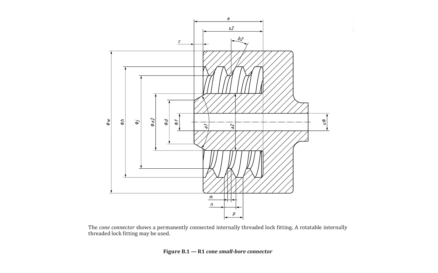
ISO 80369-2 Figure B.1 R1 Cone Small-Bore Connector
ISO 80369-2 Figure B.1 R1 Cone Small-Bore Connector identifies the male R1 cone role for Figure B.1. Use it to confirm mating connector side, lock interface, related test method, calibration scope and RFQ information before quotation.
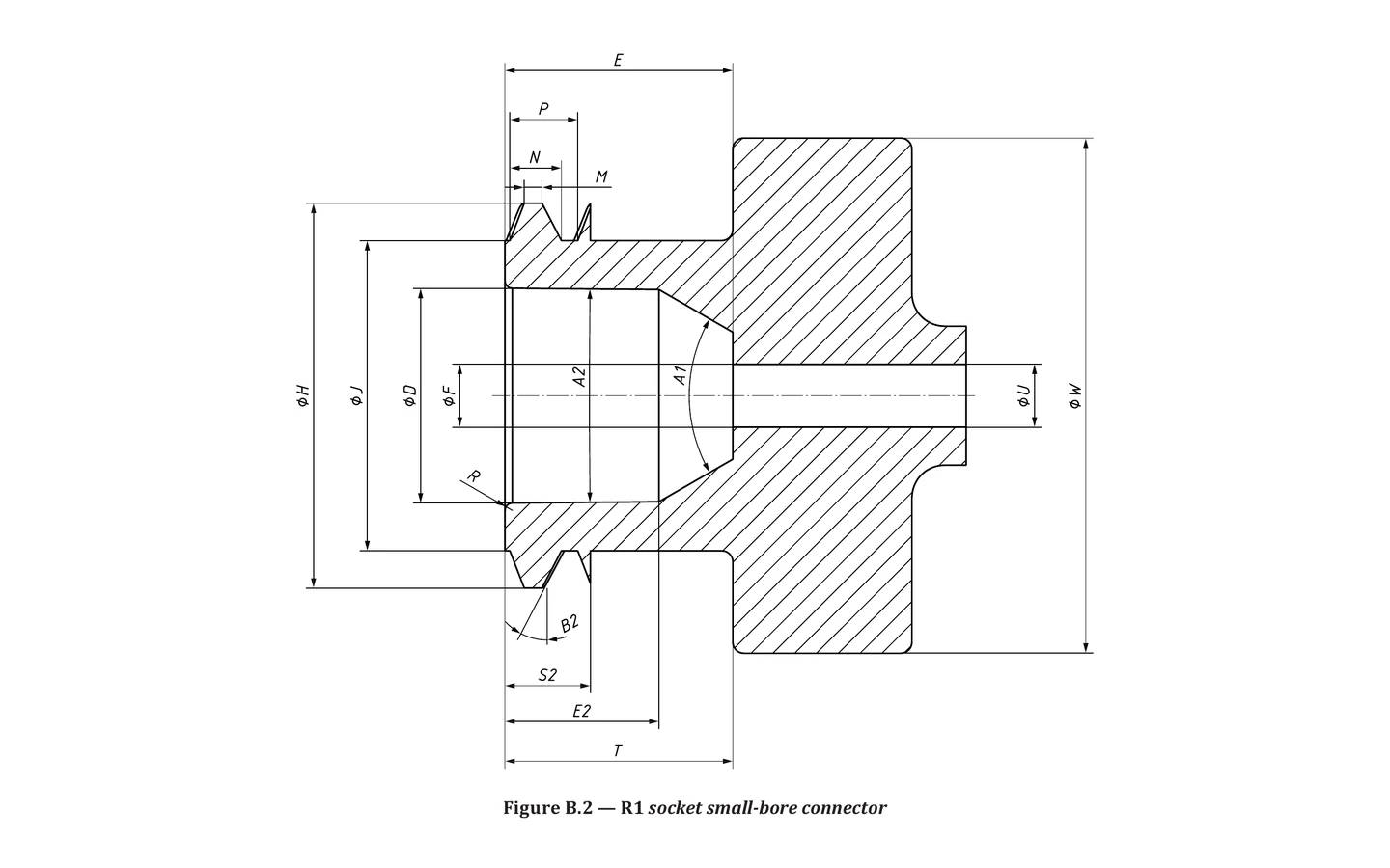
ISO 80369-2 Figure B.2 R1 Socket Small-Bore Connector
ISO 80369-2 Figure B.2 R1 Socket Small-Bore Connector identifies the female R1 socket role for Figure B.2. Use it to confirm mating connector side, lock interface, related test method, calibration scope and RFQ information before quotation.
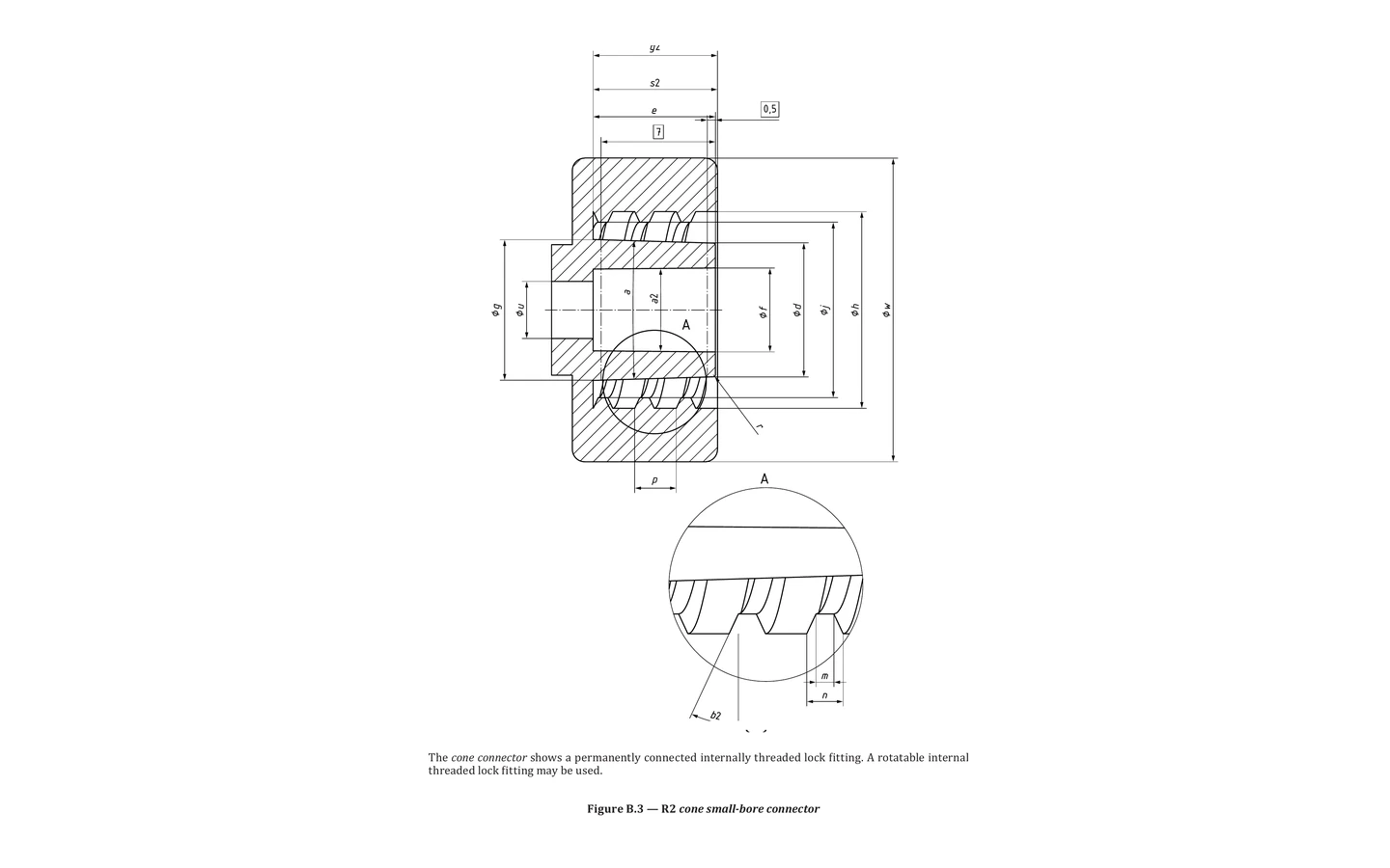
ISO 80369-2 Figure B.3 R2 Cone Small-Bore Connector
ISO 80369-2 Figure B.3 R2 Cone Small-Bore Connector identifies the male R2 cone role for Figure B.3. Use it to confirm mating connector side, lock interface, related test method, calibration scope and RFQ information before quotation.
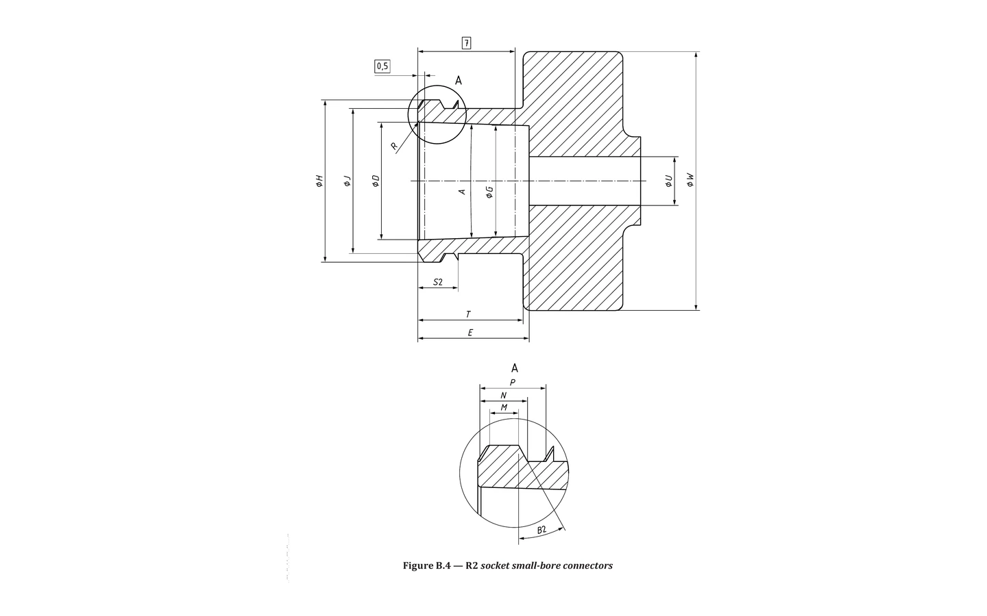
ISO 80369-2 Figure B.4 R2 Socket Small-Bore Connector
ISO 80369-2 Figure B.4 R2 Socket Small-Bore Connector identifies the female R2 socket role for Figure B.4. Use it to confirm mating connector side, lock interface, related test method, calibration scope and RFQ information before quotation.
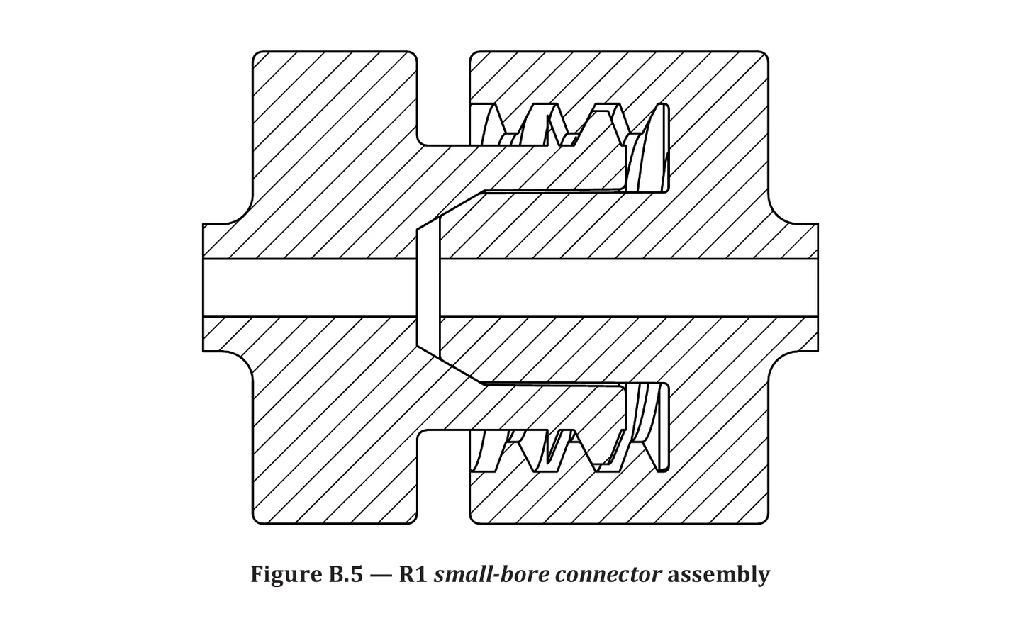
ISO 80369-2 Figure B.5 R1 Small-Bore Connector Assembly
ISO 80369-2 Figure B.5 R1 Small-Bore Connector Assembly identifies the assembly R1 connector assembly role for Figure B.5. Use it to confirm mating connector side, assembly interface, related test method, calibration scope and RFQ information before quotation.
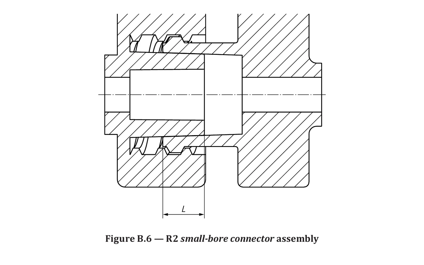
ISO 80369-2 Figure B.6 R2 Small-Bore Connector Assembly
ISO 80369-2 Figure B.6 R2 Small-Bore Connector Assembly identifies the assembly R2 connector assembly role for Figure B.6. Use it to confirm mating connector side, assembly interface, related test method, calibration scope and RFQ information before quotation.
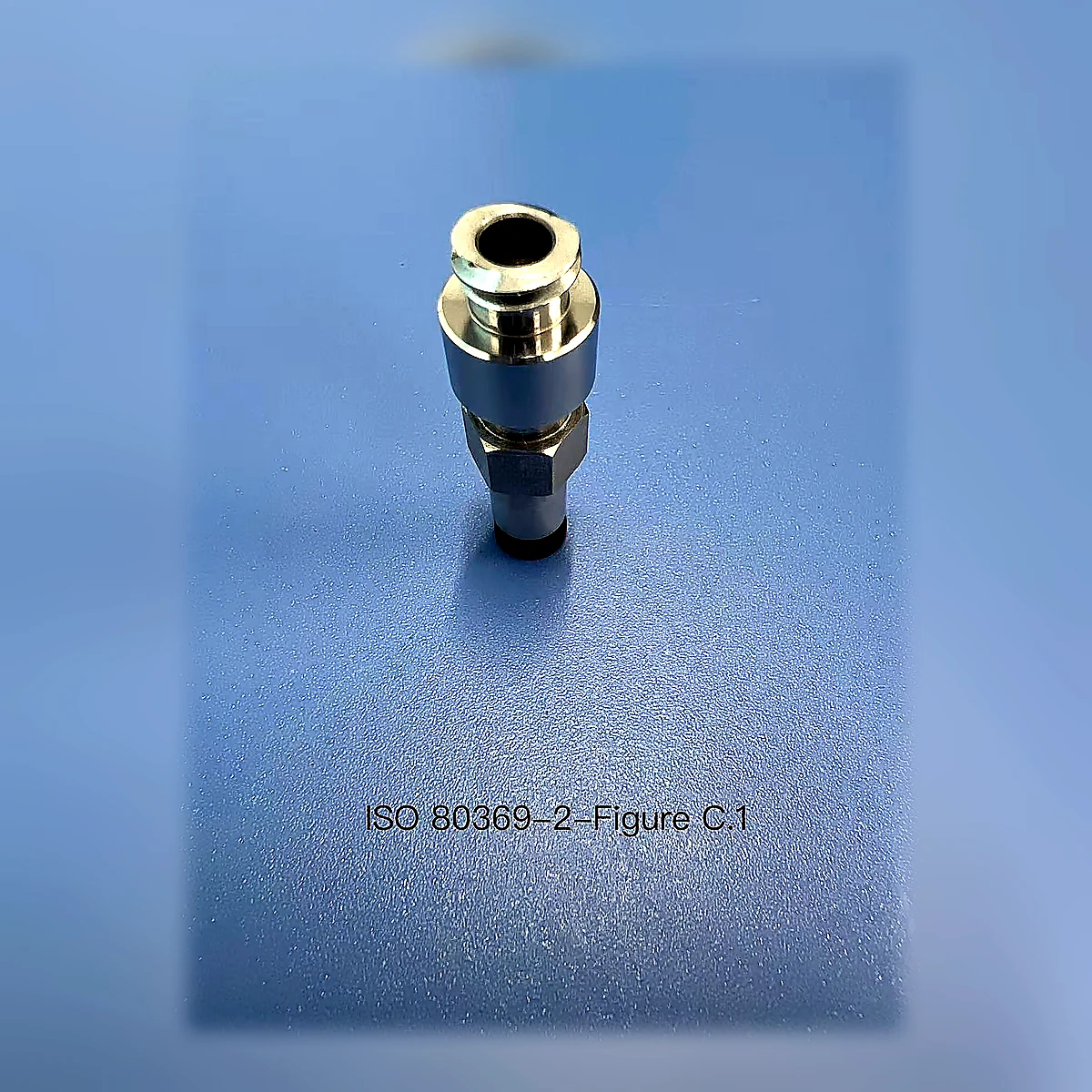
ISO 80369-2 Figure C.1 R1 Socket Reference Connector
ISO 80369-2 Figure C.1 R1 Socket Reference Connector identifies the female R1 socket role for Figure C.1. Use it to confirm mating connector side, lock interface, related test method, calibration scope and RFQ information before quotation.
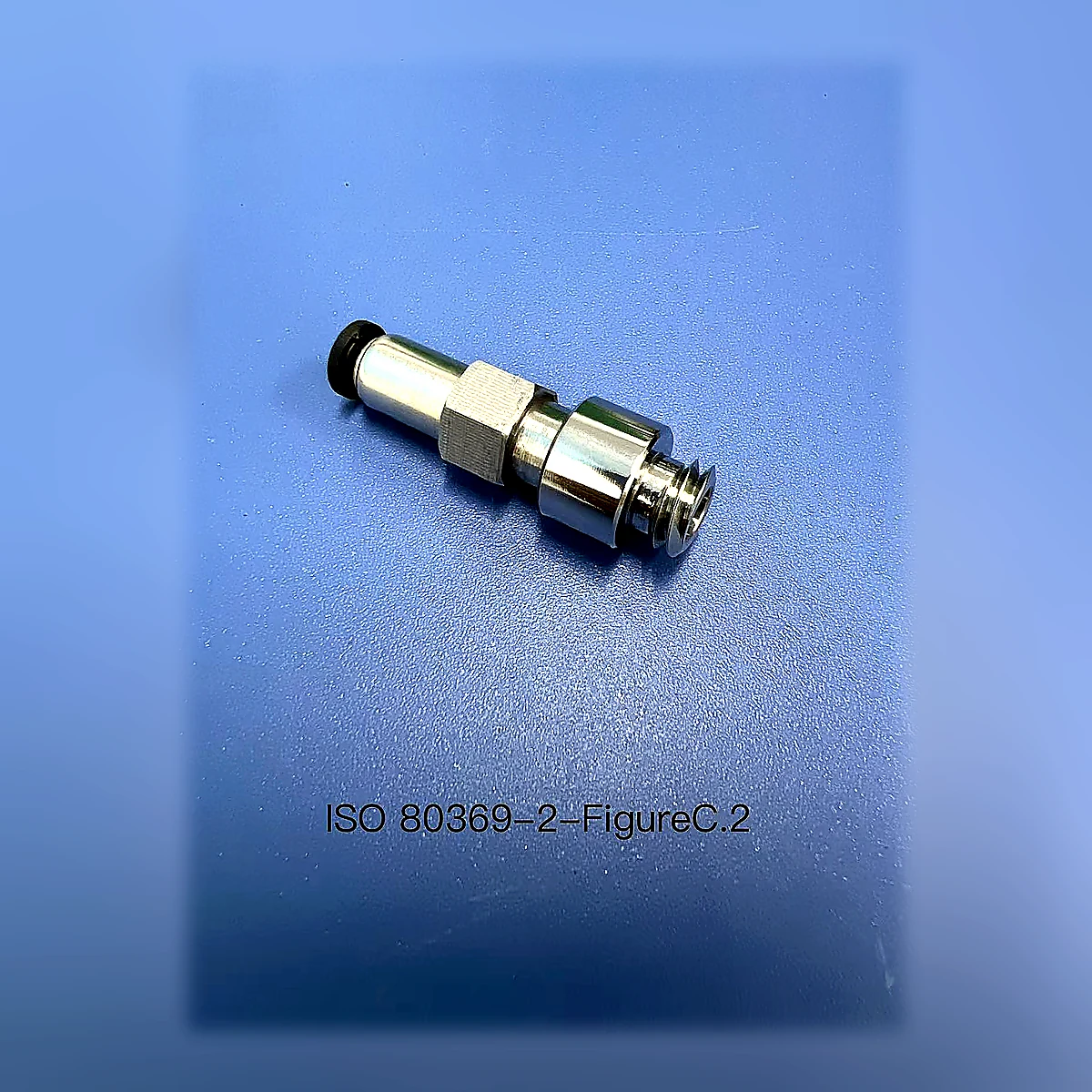
ISO 80369-2 Figure C.2 R1 Axial-Load Socket Reference Connector
ISO 80369-2 Figure C.2 R1 Axial-Load Socket Reference Connector identifies the female R1 socket role for Figure C.2. Use it to confirm mating connector side, lock interface, related test method, calibration scope and RFQ information before quotation.
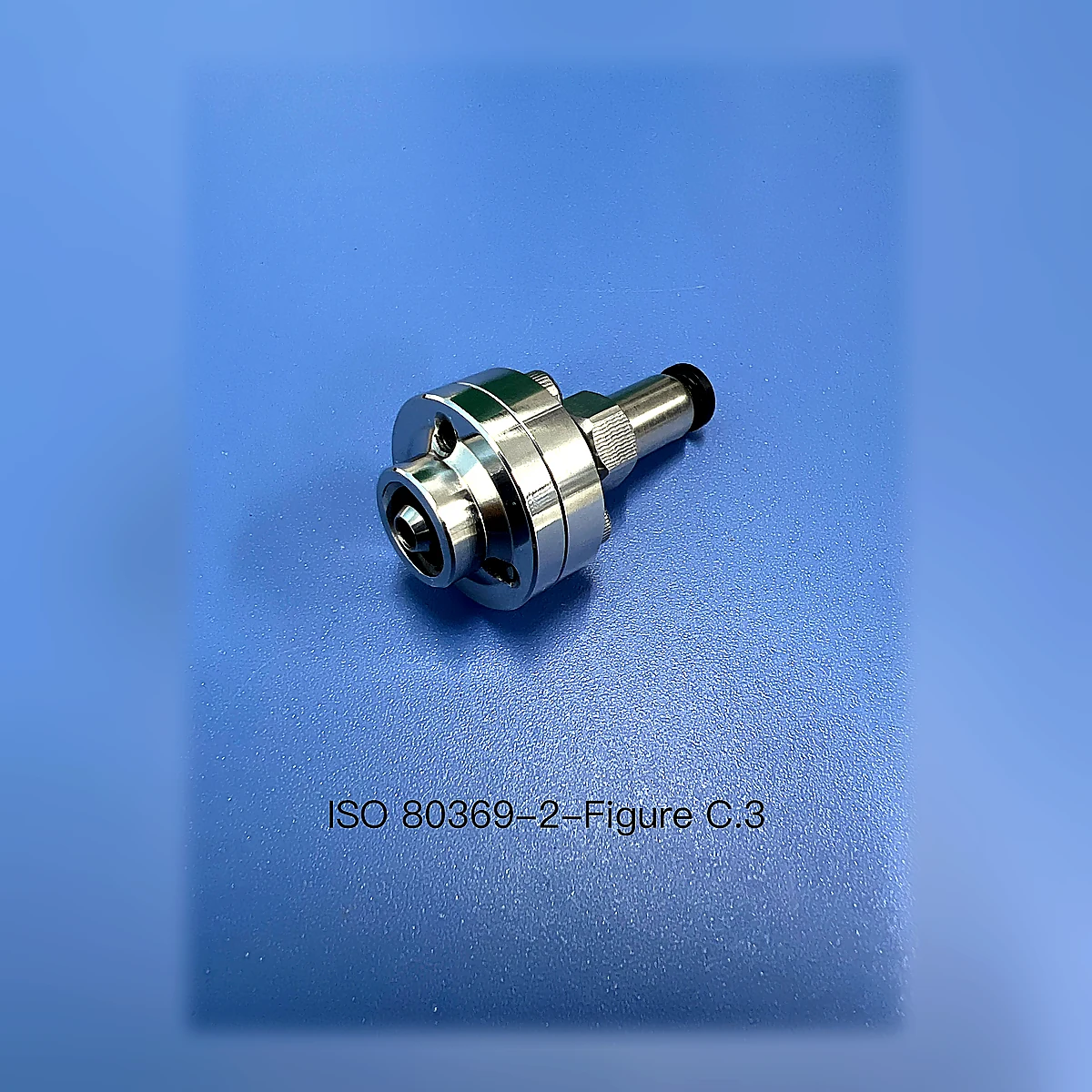
ISO 80369-2 Figure C.3 R1 Cone Reference Connector Assembly
ISO 80369-2 Figure C.3 R1 Cone Reference Connector Assembly identifies the male R1 cone role for Figure C.3. Use it to confirm mating connector side, lock interface, related test method, calibration scope and RFQ information before quotation.
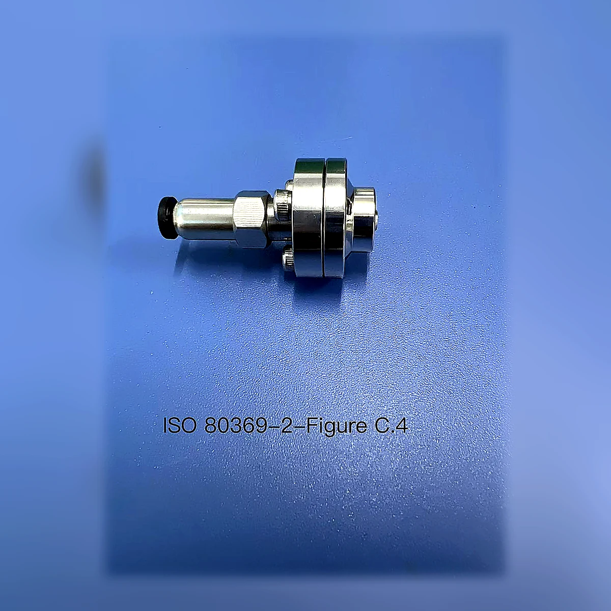
ISO 80369-2 Figure C.4 R1 Axial-Load Cone Reference Connector Assembly
ISO 80369-2 Figure C.4 R1 Axial-Load Cone Reference Connector Assembly identifies the male R1 cone role for Figure C.4. Use it to confirm mating connector side, lock interface, related test method, calibration scope and RFQ information before quotation.
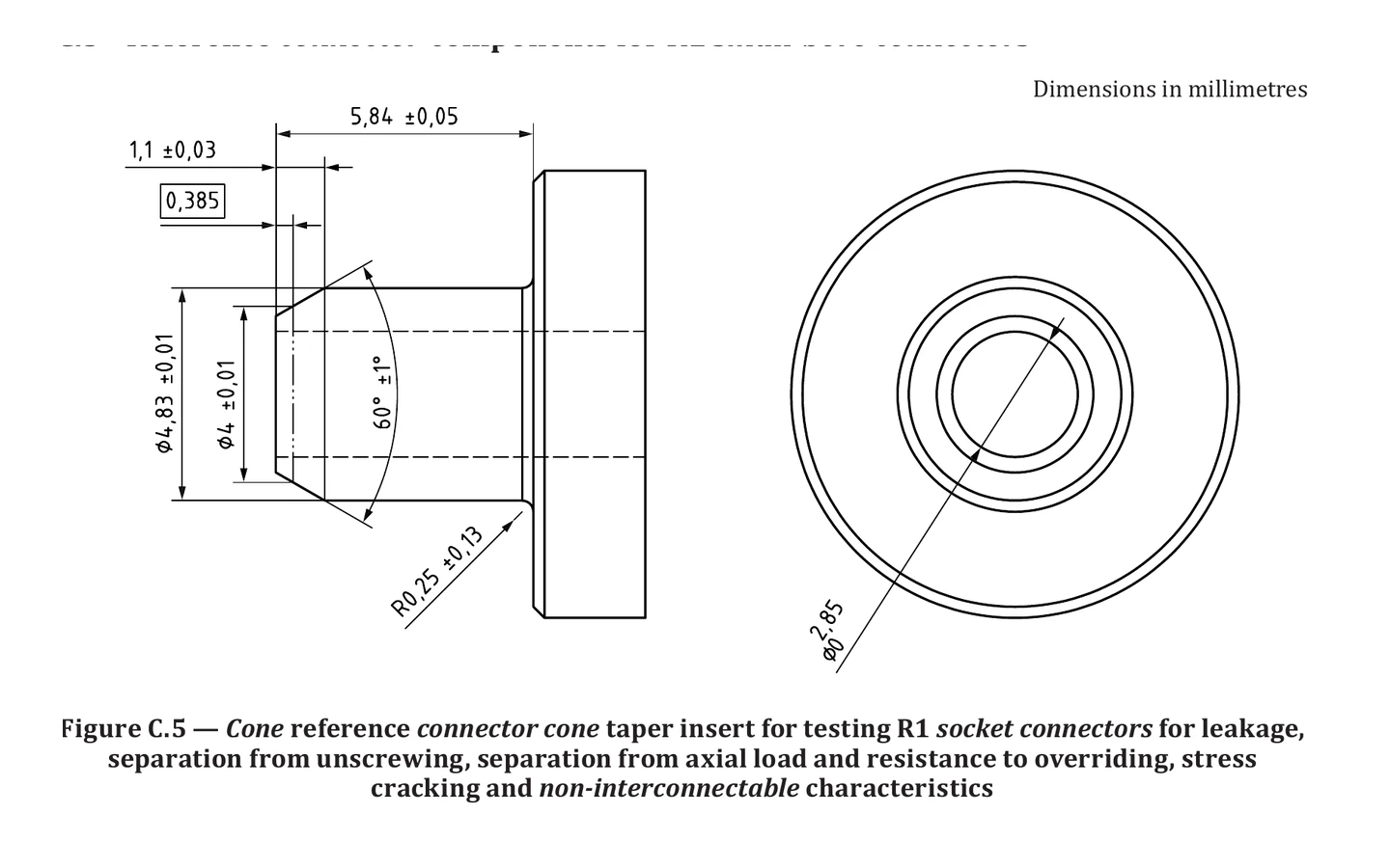
ISO 80369-2 Figure C.5 R1 Cone Taper Insert
ISO 80369-2 Figure C.5 R1 Cone Taper Insert identifies the male R1 cone insert role for Figure C.5. Use it to confirm mating connector side, component interface, related test method, calibration scope and RFQ information before quotation.
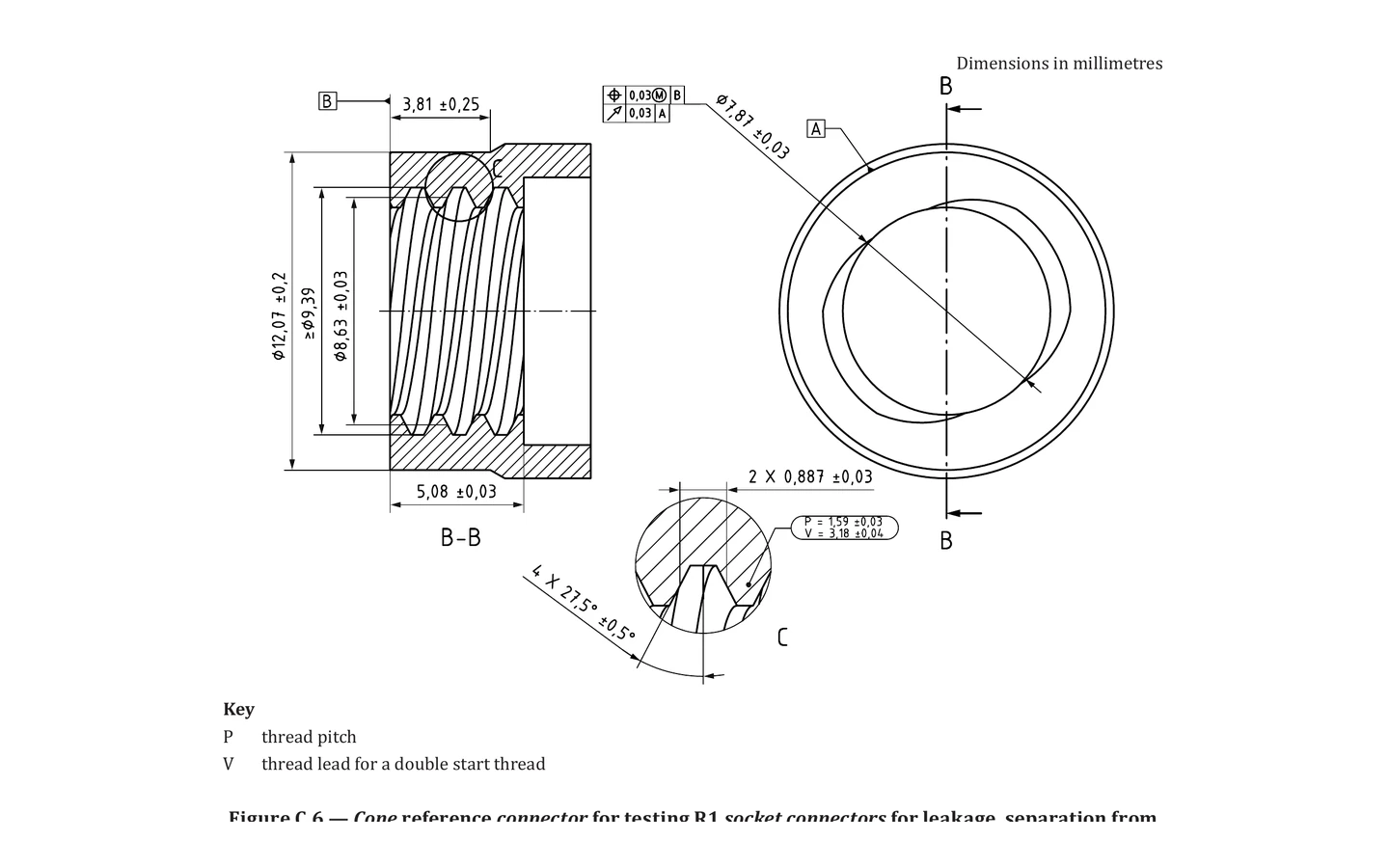
ISO 80369-2 Figure C.6 R1 Cone Reference Connector Body
ISO 80369-2 Figure C.6 R1 Cone Reference Connector Body identifies the male R1 cone body role for Figure C.6. Use it to confirm mating connector side, lock interface, related test method, calibration scope and RFQ information before quotation.
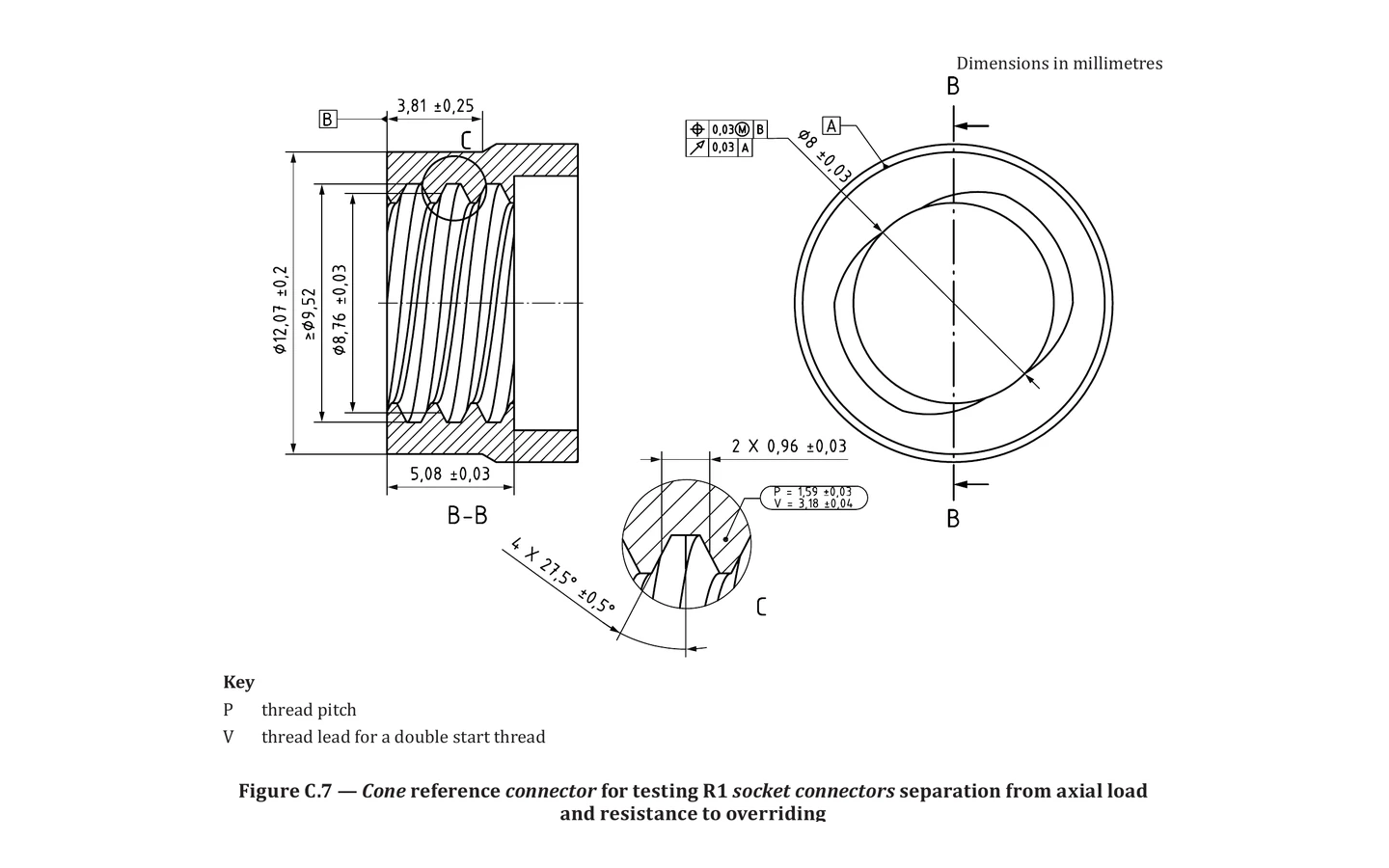
ISO 80369-2 Figure C.7 R1 Axial-Load Cone Reference Connector Body
ISO 80369-2 Figure C.7 R1 Axial-Load Cone Reference Connector Body identifies the male R1 cone body role for Figure C.7. Use it to confirm mating connector side, lock interface, related test method, calibration scope and RFQ information before quotation.
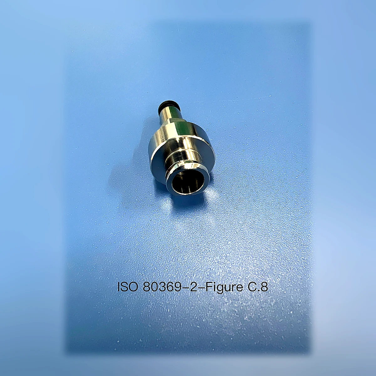
ISO 80369-2 Figure C.8 R2 Socket Reference Lock Connector
ISO 80369-2 Figure C.8 R2 Socket Reference Lock Connector identifies the female R2 socket role for Figure C.8. Use it to confirm mating connector side, lock interface, related test method, calibration scope and RFQ information before quotation.
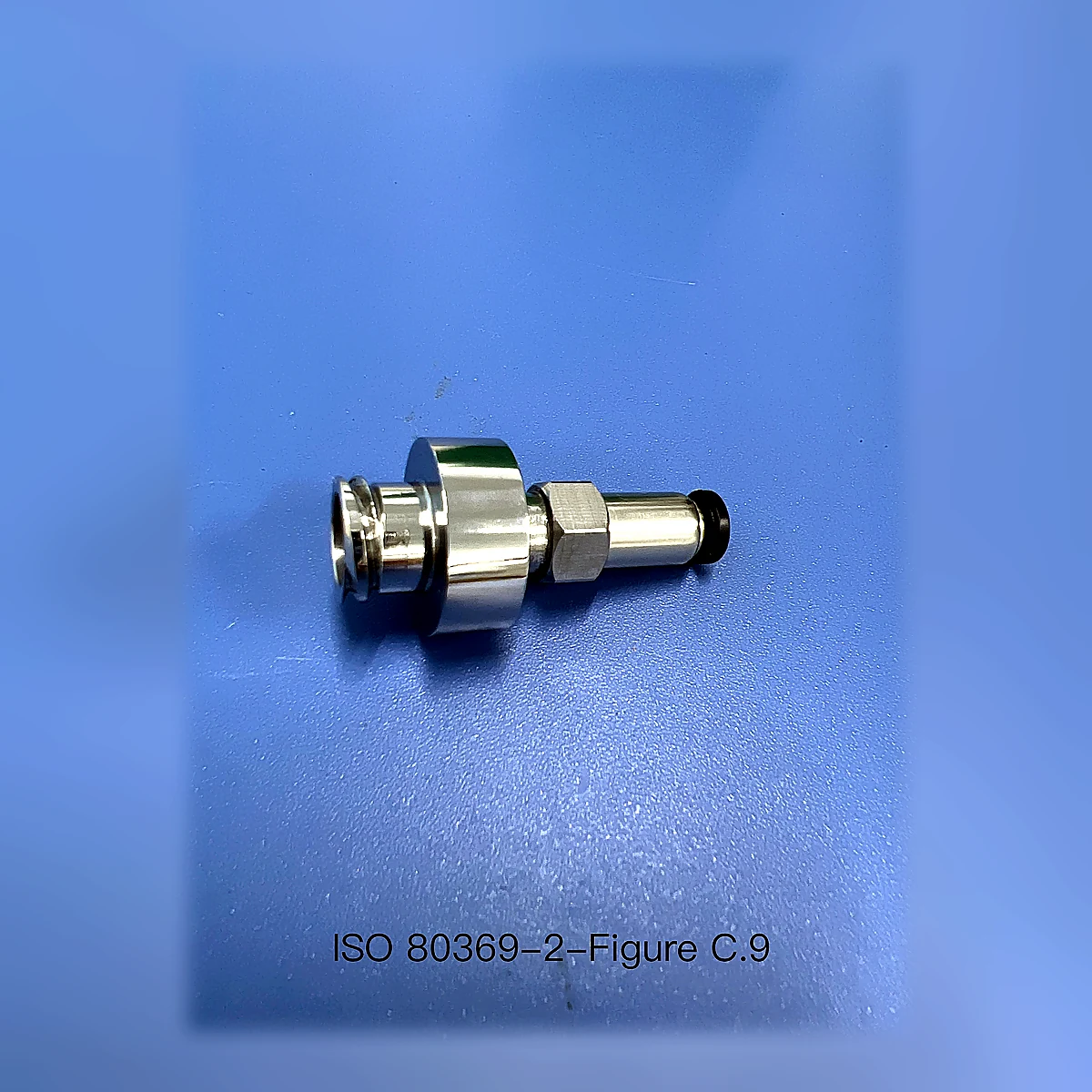
ISO 80369-2 Figure C.9 R2 Axial-Load Socket Reference Connector
ISO 80369-2 Figure C.9 R2 Axial-Load Socket Reference Connector identifies the female R2 socket role for Figure C.9. Use it to confirm mating connector side, lock interface, related test method, calibration scope and RFQ information before quotation.
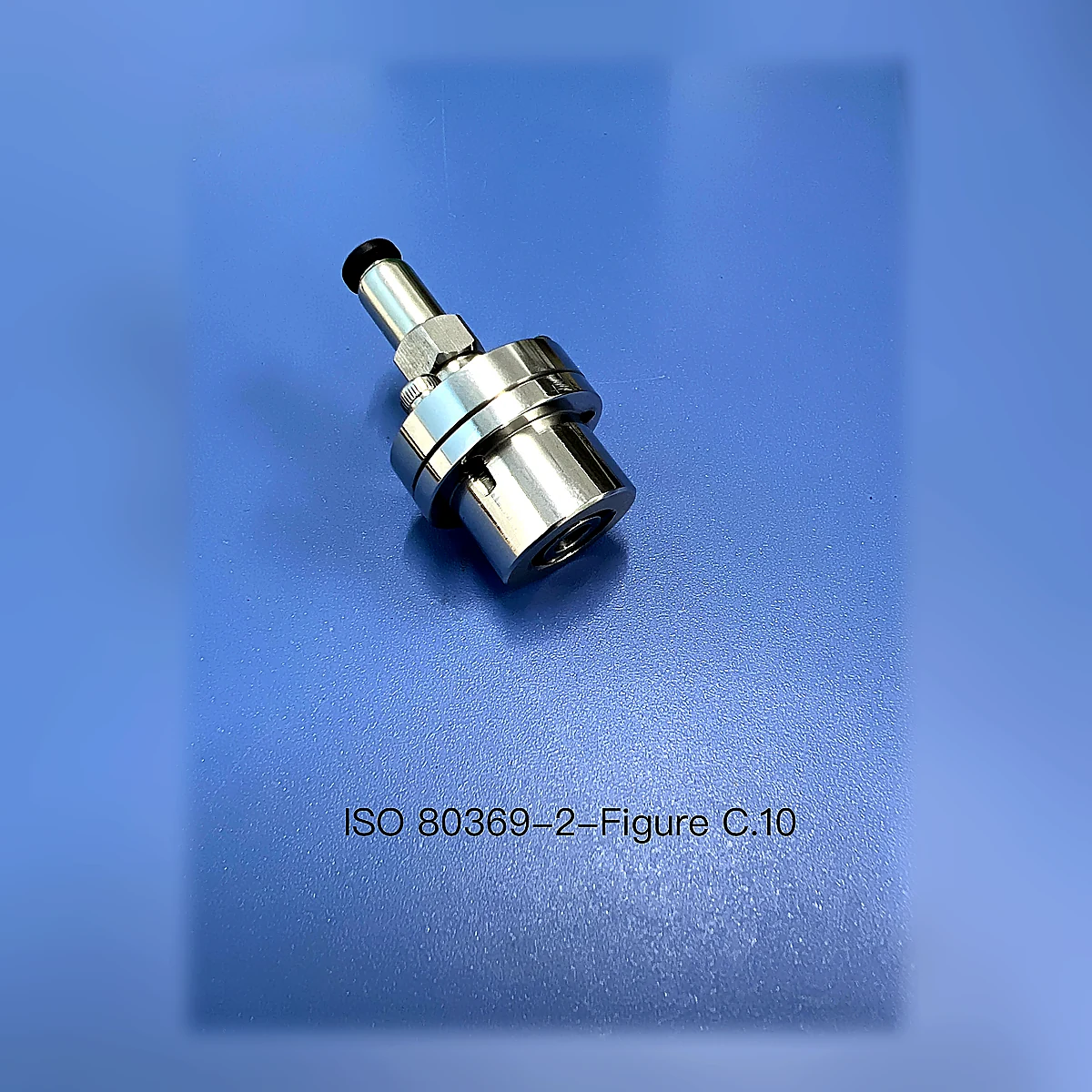
ISO 80369-2 Figure C.10 R2 Cone Reference Lock Connector Assembly
ISO 80369-2 Figure C.10 R2 Cone Reference Lock Connector Assembly identifies the male R2 cone role for Figure C.10. Use it to confirm mating connector side, lock interface, related test method, calibration scope and RFQ information before quotation.
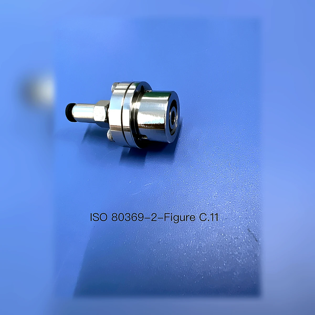
ISO 80369-2 Figure C.11 R2 Axial-Load Cone Reference Connector Assembly
ISO 80369-2 Figure C.11 R2 Axial-Load Cone Reference Connector Assembly identifies the male R2 cone role for Figure C.11. Use it to confirm mating connector side, lock interface, related test method, calibration scope and RFQ information before quotation.
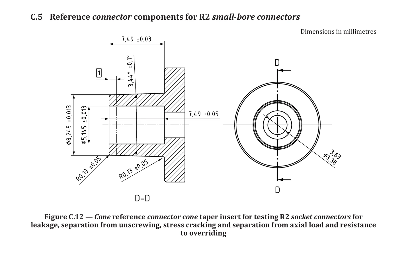
ISO 80369-2 Figure C.12 R2 Cone Taper Insert
ISO 80369-2 Figure C.12 R2 Cone Taper Insert identifies the male R2 cone insert role for Figure C.12. Use it to confirm mating connector side, component interface, related test method, calibration scope and RFQ information before quotation.
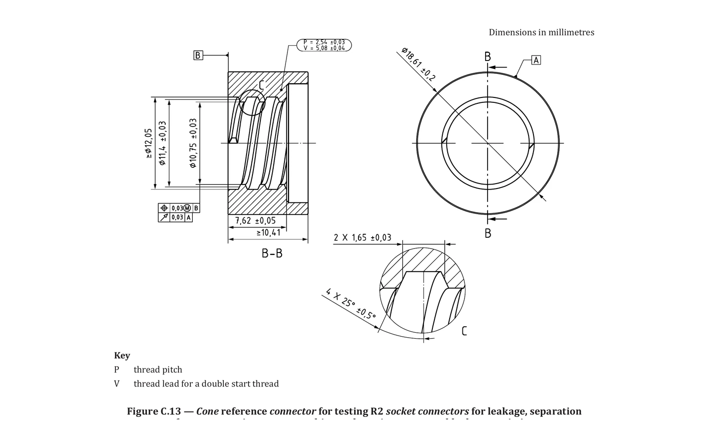
ISO 80369-2 Figure C.13 R2 Cone Reference Connector Body
ISO 80369-2 Figure C.13 R2 Cone Reference Connector Body identifies the male R2 cone body role for Figure C.13. Use it to confirm mating connector side, lock interface, related test method, calibration scope and RFQ information before quotation.
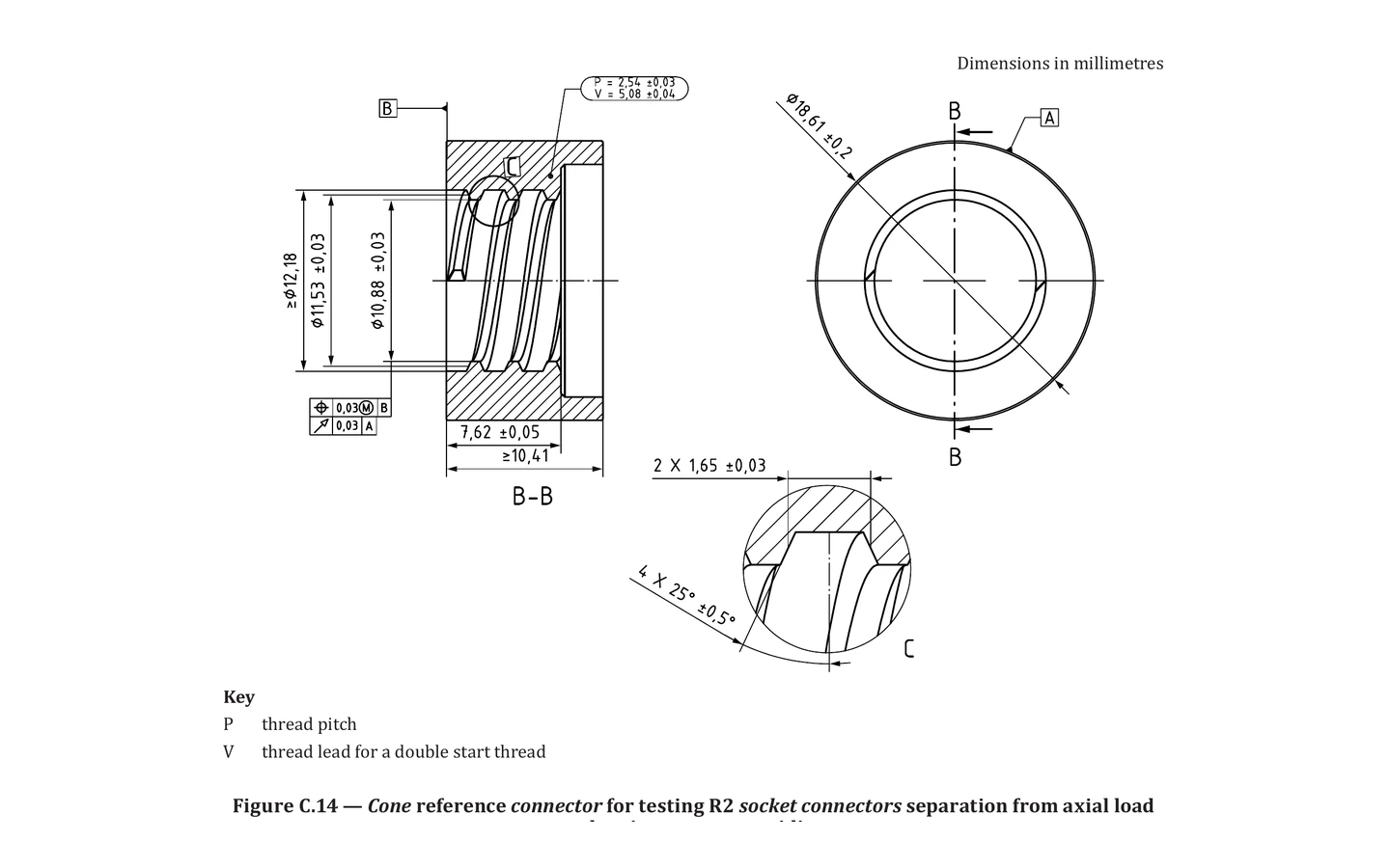
ISO 80369-2 Figure C.14 R2 Axial-Load Cone Reference Connector Body
ISO 80369-2 Figure C.14 R2 Axial-Load Cone Reference Connector Body identifies the male R2 cone body role for Figure C.14. Use it to confirm mating connector side, lock interface, related test method, calibration scope and RFQ information before quotation.
Figure C.1ISO/IEC 80369-5 Figure C.1 Female-Cone Reference Connector Assembly
ISO/IEC 80369-5 Figure C.1 Female-Cone Reference Connector Assembly identifies the female S2 cone assembly role for Figure C.1. Use it to confirm mating connector side, assembly interface, related test method, calibration scope and RFQ information before quotation.
Figure C.2ISO/IEC 80369-5 Figure C.2 Male-Cone Reference Connector Assembly
ISO/IEC 80369-5 Figure C.2 Male-Cone Reference Connector Assembly identifies the male S2 cone assembly role for Figure C.2. Use it to confirm mating connector side, assembly interface, related test method, calibration scope and RFQ information before quotation.
Figure C.3ISO/IEC 80369-5 Figure C.3 Reference Connector Sleeve
ISO/IEC 80369-5 Figure C.3 Reference Connector Sleeve identifies the not applicable S2 sleeve role for Figure C.3. Use it to confirm mating connector side, component interface, related test method, calibration scope and RFQ information before quotation.
Figure C.4ISO/IEC 80369-5 Figure C.4 Female-Cone Reference Connector Insert
ISO/IEC 80369-5 Figure C.4 Female-Cone Reference Connector Insert identifies the female S2 cone insert role for Figure C.4. Use it to confirm mating connector side, component interface, related test method, calibration scope and RFQ information before quotation.
Figure C.5ISO/IEC 80369-5 Figure C.5 Male-Cone Reference Connector Insert
ISO/IEC 80369-5 Figure C.5 Male-Cone Reference Connector Insert identifies the male S2 cone insert role for Figure C.5. Use it to confirm mating connector side, component interface, related test method, calibration scope and RFQ information before quotation.
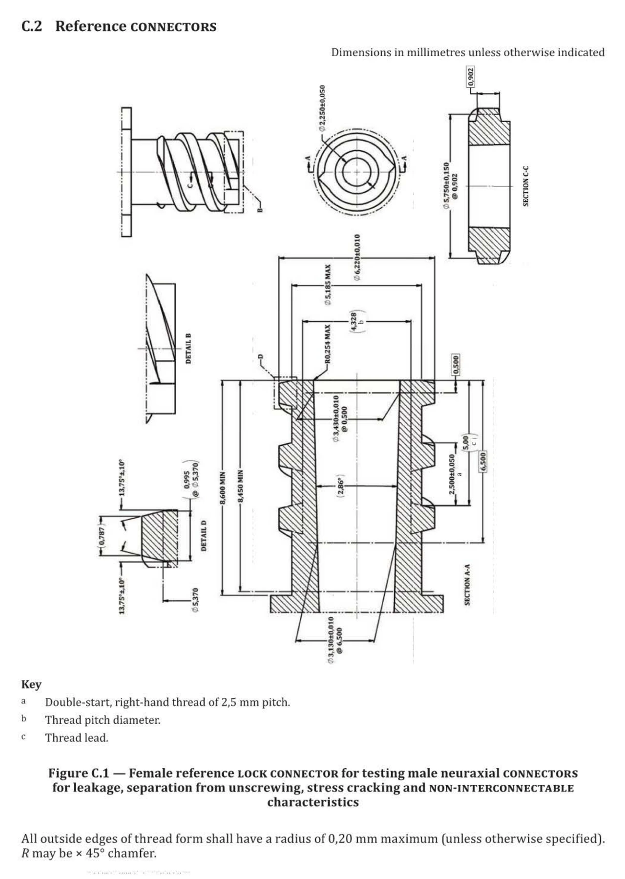
ISO 80369-6 Figure C.1 Female Neuraxial Reference Lock Connector
ISO 80369-6 Figure C.1 Female Neuraxial Reference Lock Connector identifies the female neuraxial role for Figure C.1. Use it to confirm mating connector side, lock interface, related test method, calibration scope and RFQ information before quotation.
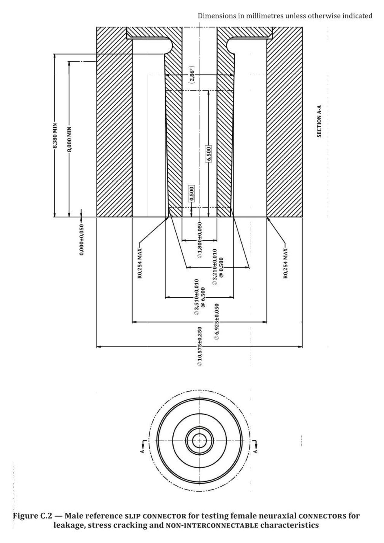
ISO 80369-6 Figure C.2 Male Neuraxial Reference Slip Connector
ISO 80369-6 Figure C.2 Male Neuraxial Reference Slip Connector identifies the male neuraxial role for Figure C.2. Use it to confirm mating connector side, slip interface, related test method, calibration scope and RFQ information before quotation.
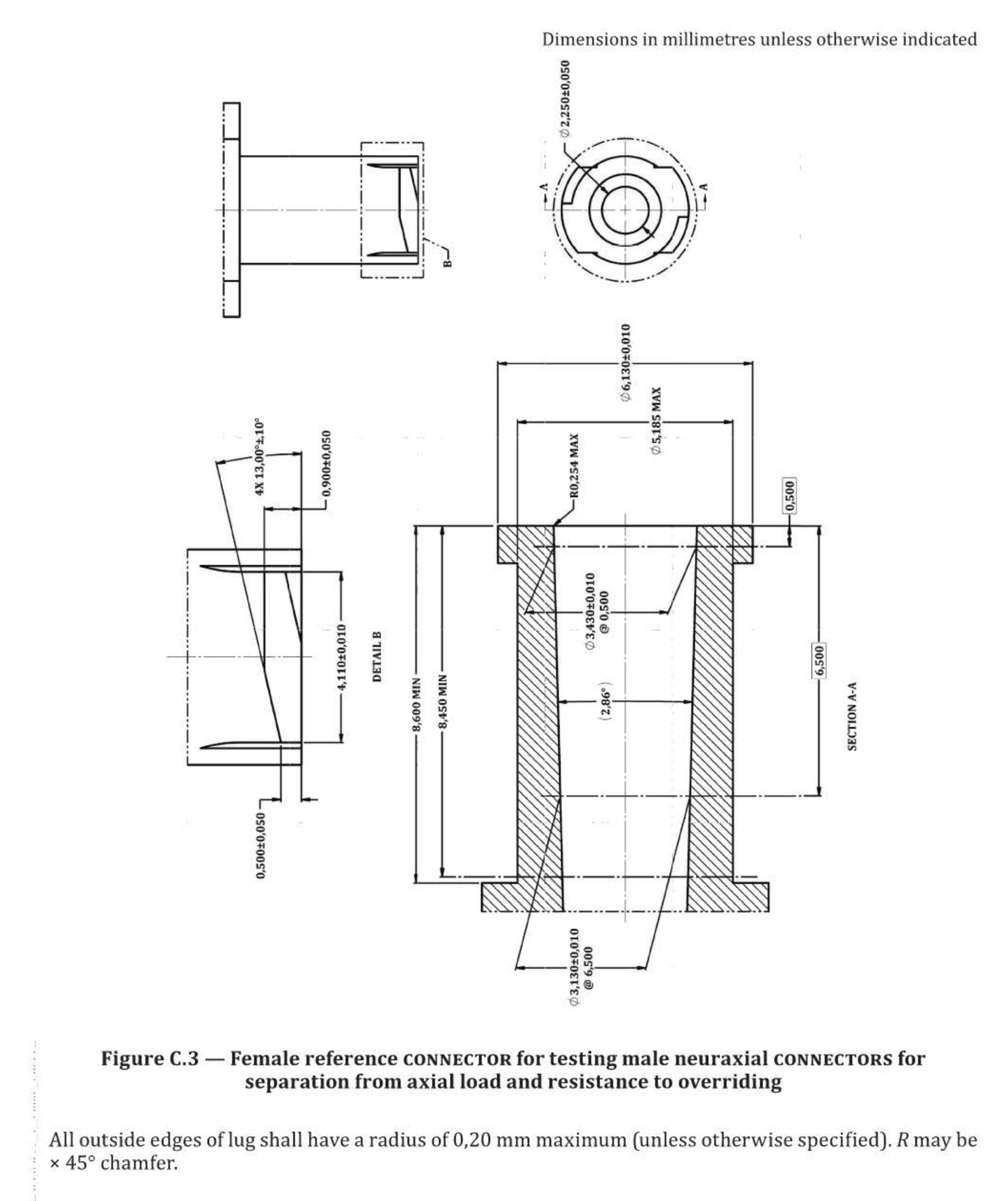
ISO 80369-6 Figure C.3 Female Axial-Load Neuraxial Reference Connector
ISO 80369-6 Figure C.3 Female Axial-Load Neuraxial Reference Connector identifies the female neuraxial role for Figure C.3. Use it to confirm mating connector side, lock interface, related test method, calibration scope and RFQ information before quotation.
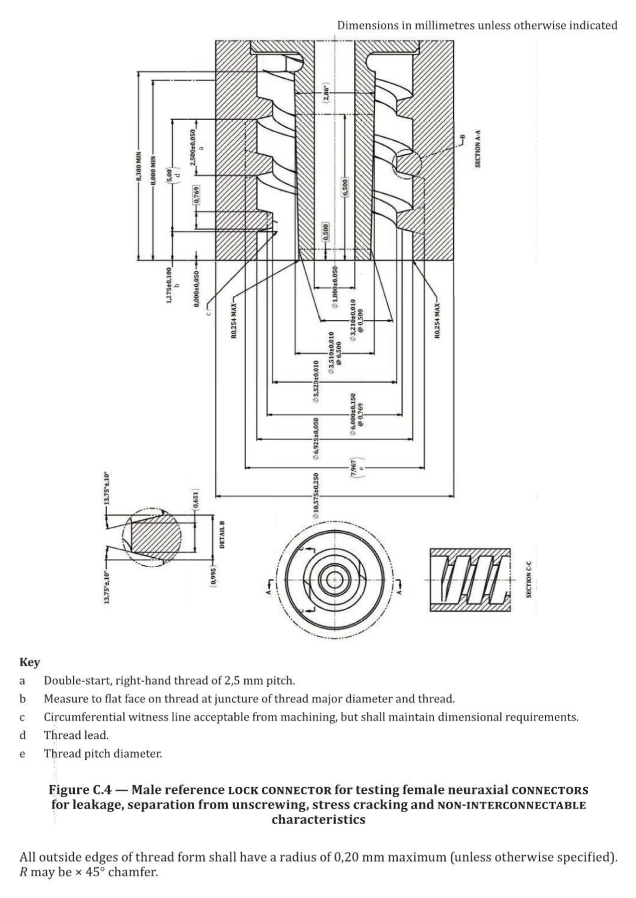
ISO 80369-6 Figure C.4 Male Neuraxial Reference Lock Connector
ISO 80369-6 Figure C.4 Male Neuraxial Reference Lock Connector identifies the male neuraxial role for Figure C.4. Use it to confirm mating connector side, lock interface, related test method, calibration scope and RFQ information before quotation.
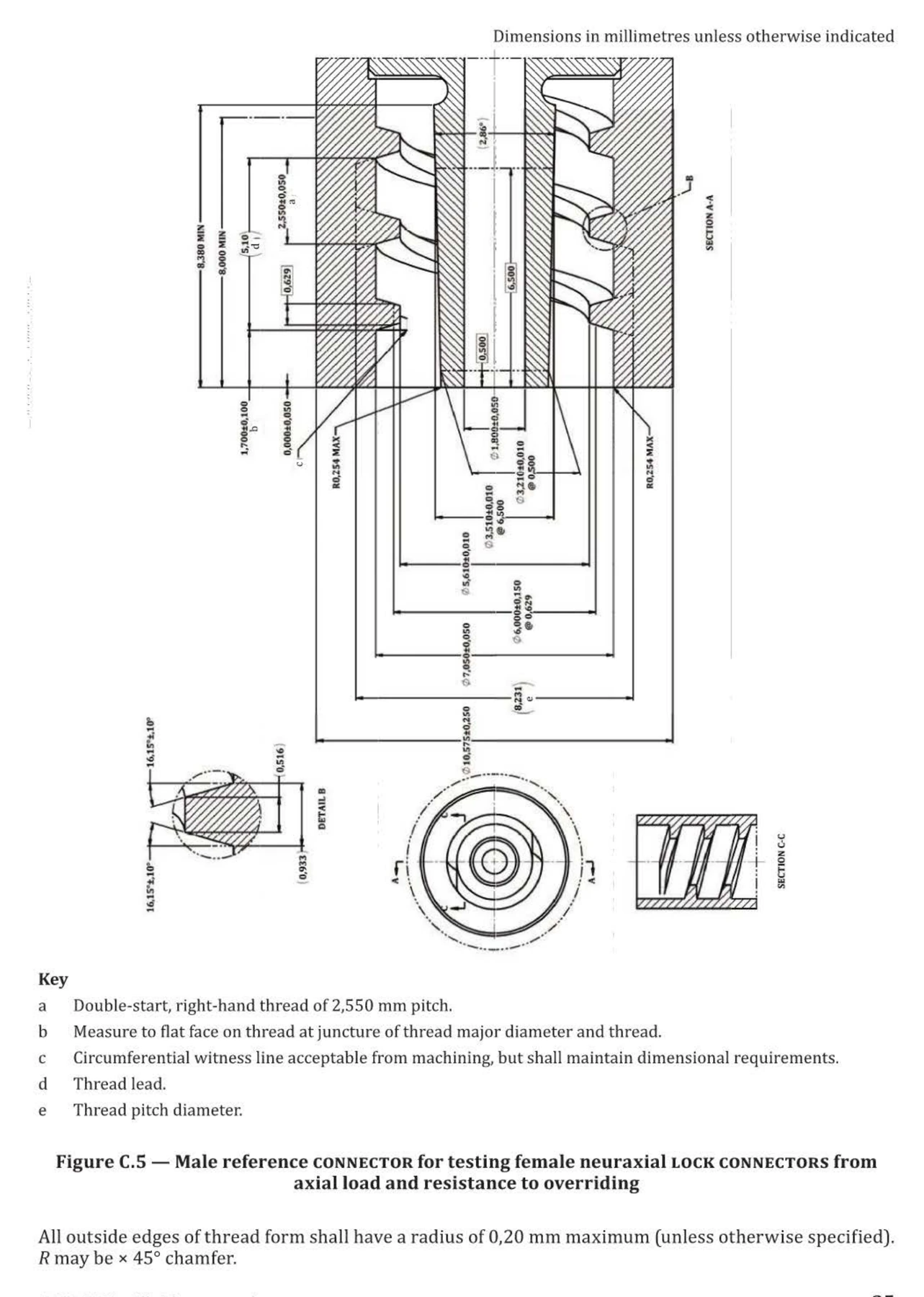
ISO 80369-6 Figure C.5 Male Axial-Load Neuraxial Reference Connector
ISO 80369-6 Figure C.5 Male Axial-Load Neuraxial Reference Connector identifies the male neuraxial role for Figure C.5. Use it to confirm mating connector side, lock interface, related test method, calibration scope and RFQ information before quotation.
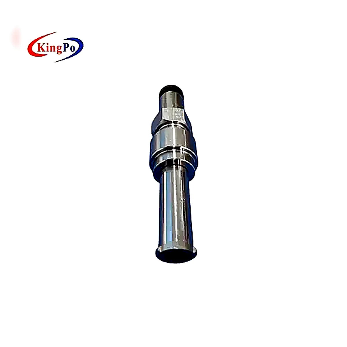
ISO 80369-7 Figure C.1 Female Reference Luer Lock Connector
ISO 80369-7 Figure C.1 Female Reference Luer Lock Connector identifies the female Luer role for Figure C.1. Use it to confirm mating connector side, lock interface, related test method, calibration scope and RFQ information before quotation.
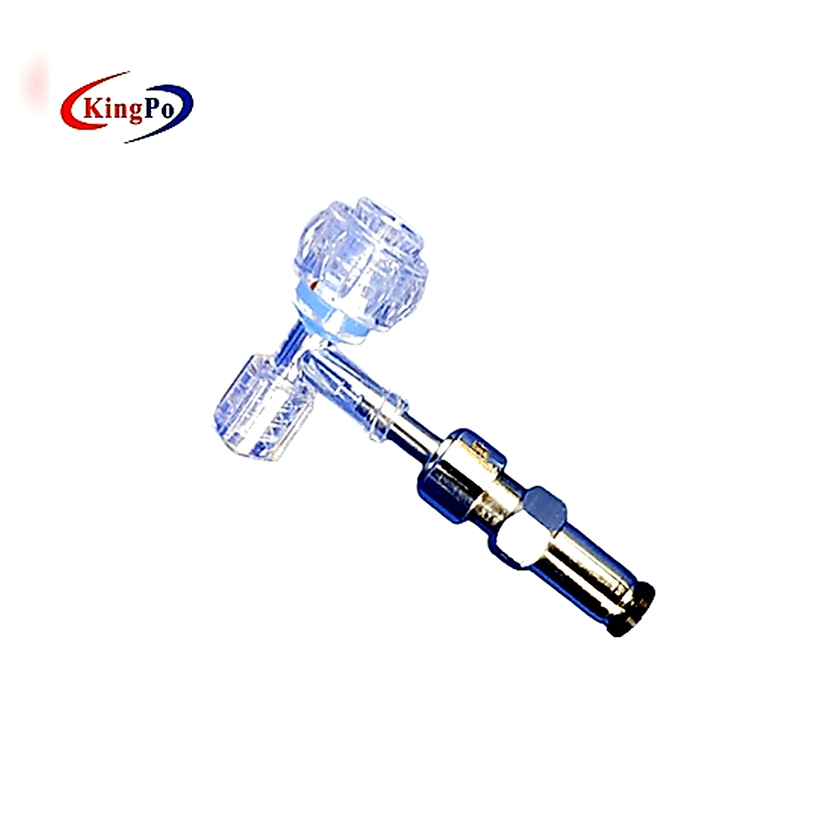
ISO 80369-7 Figure C.2 Male Reference Luer Slip Connector
ISO 80369-7 Figure C.2 Male Reference Luer Slip Connector identifies the male Luer role for Figure C.2. Use it to confirm mating connector side, slip interface, related test method, calibration scope and RFQ information before quotation.
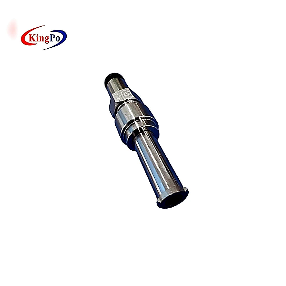
ISO 80369-7 Figure C.3 Female Axial-Load Reference Luer Lock Connector
ISO 80369-7 Figure C.3 Female Axial-Load Reference Luer Lock Connector identifies the female Luer role for Figure C.3. Use it to confirm mating connector side, lock interface, related test method, calibration scope and RFQ information before quotation.
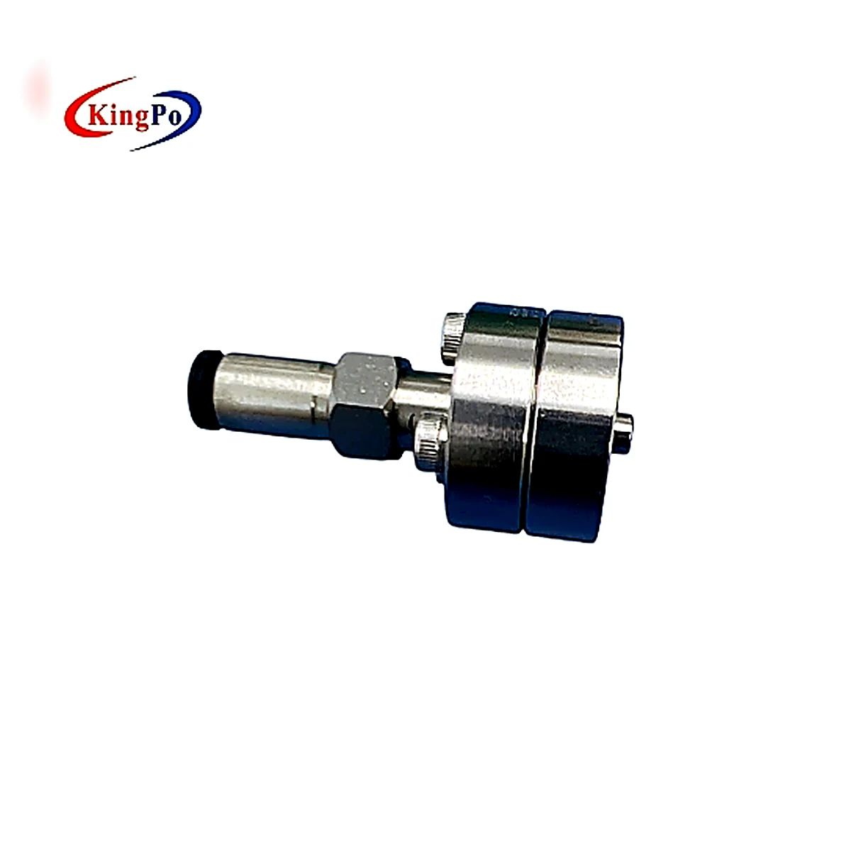
ISO 80369-7 Figure C.4 Male Reference Luer Lock Connector
ISO 80369-7 Figure C.4 Male Reference Luer Lock Connector identifies the male Luer role for Figure C.4. Use it to confirm mating connector side, lock interface, related test method, calibration scope and RFQ information before quotation.
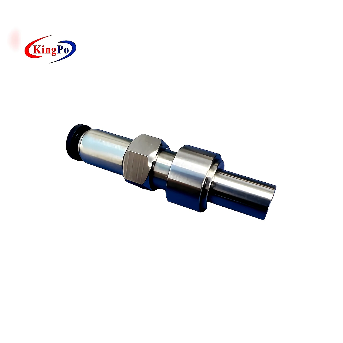
ISO 80369-7 Figure C.5 Female Reference Luer Slip Connector
ISO 80369-7 Figure C.5 Female Reference Luer Slip Connector identifies the female Luer role for Figure C.5. Use it to confirm mating connector side, slip interface, related test method, calibration scope and RFQ information before quotation.
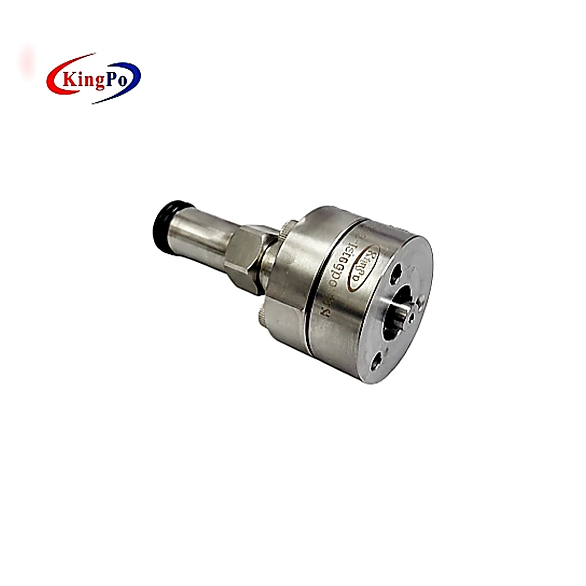
ISO 80369-7 Figure C.6 Male Axial-Load Reference Luer Lock Connector
ISO 80369-7 Figure C.6 Male Axial-Load Reference Luer Lock Connector identifies the male Luer role for Figure C.6. Use it to confirm mating connector side, lock interface, related test method, calibration scope and RFQ information before quotation.
Related standards, requirements and test methods
Confirm the applicable standard, product family and test method, then include the required quantity, fixtures and documents with your inquiry.
ISO 80369-2:2024
Match ISO 80369-2 Figures with respiratory reference connectors, mating sides, applicable methods and quotation requirements.
IEC 80369-5
Limb cuff inflation connector relationship guide for IEC 80369-5 selection, reference connector context and RFQ preparation.
ISO 80369-6
Neuraxial connector relationship guide and product links.
ISO 80369-7
Luer gauge, luer reference connector, and related equipment relationships.
Limb Cuff Reference Connector Requirement
Illustrative ISO 80369-5 relationship note for reference connector selection.
Neuraxial Reference Connector Requirement
Illustrative ISO 80369-6 relationship note for reference connector selection.
Air Pressure Leakage
Method page for air pressure leakage workflows.
ISO 80369-20 Annex D Subatmospheric Pressure Leakage
Method page for ISO 80369-20 Annex D subatmospheric-pressure air leakage equipment, connector setup questions and reporting boundaries.