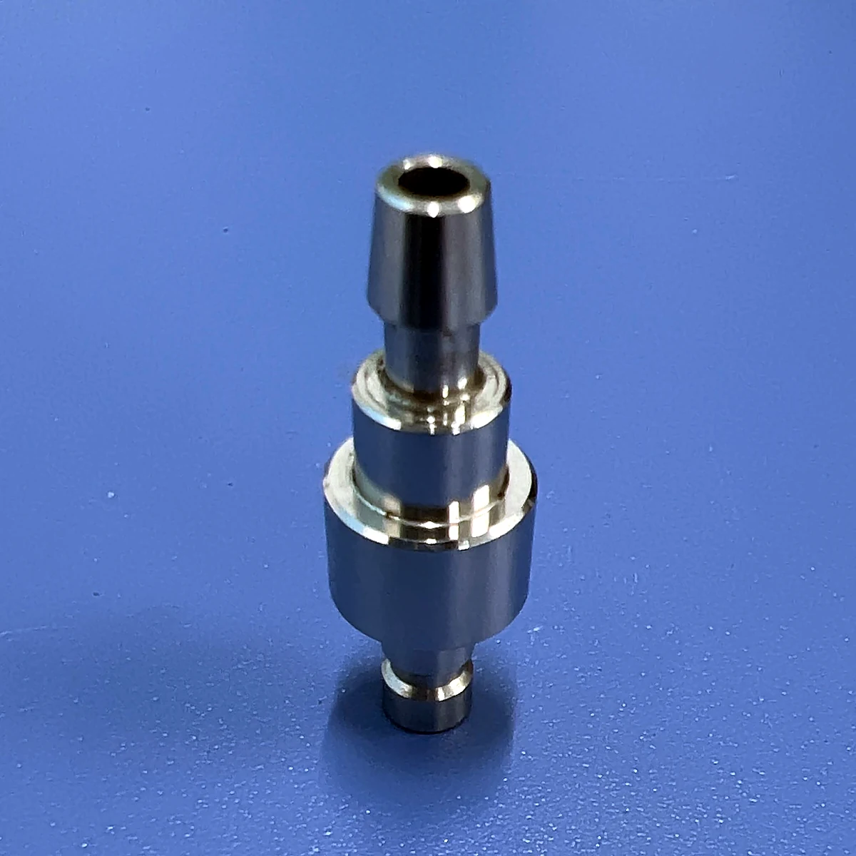
Clause 5.1 is short. A connector joining a cuff to a sphygmomanometer for an adult or paediatric patient shall comply with Figure B.1 and Table B.1 for the male S1 connector and Figure B.2 and Table B.2 for the female S1 connector. The cuff connector shall be the male connector. Conformity is checked by verifying the dimensions and tolerances of the normative Annex B. Annex H records the connectors that were formerly used for this purpose and are no longer permitted.
Table B.1. Male S1 connector
All dimensions are in millimetres unless otherwise stated. Values in parentheses are reference dimensions.
| Symbol | Description | Minimum | Nominal | Maximum |
|---|---|---|---|---|
| b5 | Side angle of the locking groove, degrees | 44.0° | 45.0° | 46.0° |
| e | Length of the male bayonet pin | 8.400 | 8.500 | 8.600 |
| Øf | Inside diameter at the tip of the male pin | 2.450 | 2.675 | 2.900 |
| g5 | Width at the bottom of the locking groove | 0.910 | 1.060 | 1.210 |
| Øh5 | Outside diameter of the male pin | 4.880 | 4.930 | 4.980 |
| Øj5 | Diameter at the bottom of the pin groove | 3.810 | 3.940 | 4.070 |
| k5 | Length from the pin tip to the locking groove | 2.880 | 3.010 | 3.140 |
| (L) | Engagement length, reference (see Figure B.3) | (1.510) | (1.610) | (1.710) |
| r1 | Radius or chamfer of the outer tip of the male pin | 0.200 | 0.510 | 0.820 |
| r2 | Radius or chamfer of the inner tip of the male pin | 0.000 | 0.050 | 0.100 |
| Øu | Inside diameter of the fluid cavity | 2.450 | 2.675 | — |
| Øw | Outside diameter of the smallest circumscribed circle of the flange of the male locking connector | 6.400 | 9.000 | 11.600 |
Footnote a: the locking groove defined by b5, Øj5 and g5 may be omitted. The flange at Øw need not be a complete circle.
Øh5, 4.880 mm to 4.980 mm, is the male sealing surface. Its tolerance band is 0.100 mm wide, and the corresponding female bore ØH5 in Table B.2 is 5.060 mm to 5.150 mm. The two are separated by 0.080 mm to 0.270 mm, a gap closed by the sealing arrangement rather than by the rigid diameters. The draft states in two notes that Øh5 is the sealing surface that mates with dimension ØS5 of the female connector; Table B.2 defines ØS5 as the inside diameter at the internal sealing boundary, 4.380 mm minimum. A pin of 4.930 mm nominal cannot enter a bore of 4.380 mm, so that cross-reference should be checked against the published standard before it is used in a drawing review.
Table B.2. Female S1 connector
| Symbol | Description | Minimum | Nominal | Maximum |
|---|---|---|---|---|
| E | Depth of the female connector to the fluid cavity | 8.600 | 8.600 | — |
| ØH5 | Inside diameter of the female connector | 5.060 | 5.105 | 5.150 |
| (L) | Engagement length, reference (see Figure B.3) | (1.510) | (1.610) | (1.710) |
| M5 | Depth to the boundary of the internal seal at the end face | 6.890 | 6.890 | — |
| ØS5 | Inside diameter at the internal sealing boundary | 4.380 | 4.380 | — |
| ØU | Inside diameter of the fluid cavity | 1.061 | 2.660 | 2.900 |
| ØW | Inside diameter of the smallest cylinder enclosing the outer surface of the connector | 9.750 | 16.280 | 22.500 |
Footnote a: for a plug, a minimum ØU of 0.0 mm is permitted where no gas transmission is intended. The sealing surface at ØH need not comply with 4.2, for example where it is elastic. The outside diameter at ØW need not be a complete circle. The details of the locking mechanism engaging the male locking groove are specified by the manufacturer.
The minimum of ØW is 9.750 mm in this draft. It was 10.060 mm in IEC 80369-5:2016 before Cor 2:2021 changed it, and the foreword records the change as an editorial incorporation of that corrigendum. The quantity is an envelope condition, not a mating dimension: it constrains the smallest cylinder that can be placed over the outer form of the female connector, which matters for shrouds, caps and adjacent parts. Because it is a cylinder rather than a single cross-section, a gauge that checks one plane will not detect a local violation.
What the drawings do and do not fix
Figure B.3 shows the mated pair. The engagement length L is printed in parentheses in both tables and is therefore a reference dimension. The locking groove may be omitted, the flange and the outer form need not be circular, and the female seal may be elastic. Annex A explains the reason: the S1 connector is available from many sources worldwide, meets the technical requirements of the standard and is already accepted by users and manufacturers, but the locking and sealing mechanism described in note 2 of Figure B.2 varies between commercial products and is not specified, so no complete engineering drawing of that mechanism can be given. Annex A also records that these undefined dimensions may increase the risk of a misconnection with other small-bore connectors in the series.
Conformance is established against the dimension chains in Tables B.1 and B.2, not by comparison with a drawing or with a competitor's part. The published IEC 80369-5:2016, including Cor 1:2017 and Cor 2:2021, and the final GB/T text remain the authorities for the complete symbol lists and their footnotes.


IEC 80369-5:2016, clause-by-clause series. Part 3 of 7.