Annexes C and D are normative and unusually short. Annex C fixes what the standard connectors used in testing shall be, and Annex D points to the device standards that already define the connections on the sphygmomanometer side. Neither annex carries a dimension table in the consultation draft.
Annex C. Standard connectors
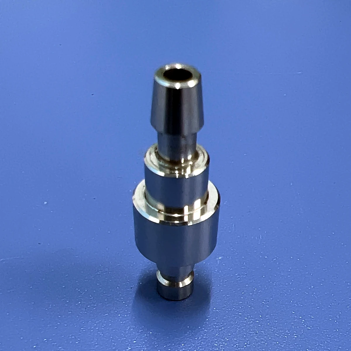
C.1 requires the standard connectors for limb cuff inflation applications to be made of a corrosion-resistant rigid material. C.2 requires the standard connectors used for leakage, resistance to axial separation and non-interconnectability to be standard connectors available on the market. Those two sentences are the whole normative annex in the draft.
The choice of a commercially available part is deliberate. Annex A records that the specified standard connector design is the S1 connector originally used by manufacturers in this application, so that all other S1 connector designs and their testing are interoperable with it. The measurement datum is therefore the original production geometry rather than a purpose-built gauge. This differs from the reference connector annexes in other parts of the ISO 80369 series, which specify modulus thresholds, surface roughness and edge radii for machined datums. Here the draft gives none of those values.
The published IEC 80369-5:2016 identifies its reference connector parts by figure numbers C.1 to C.5. The product family catalogued for this application reflects that structure: two reference connector assemblies, a sleeve, and two inserts.
| Designation | Part | Where the draft calls it up |
|---|---|---|
| Figure C.1 | Female-cone reference connector assembly | Clause 4.1, non-interconnectability; Clauses 6.1 and 6.2 |
| Figure C.2 | Male-cone reference connector assembly | Clause 4.1, non-interconnectability; Clauses 6.1 and 6.2 |
| Figure C.3 | Reference connector sleeve | Assembly of the reference connector pairs |
| Figure C.4 | Female-cone reference connector insert | Assembly of the reference connector pairs |
| Figure C.5 | Male-cone reference connector insert | Assembly of the reference connector pairs |
The assembly descriptions follow the figure designations used for the published standard. The consultation draft does not reproduce the drawings or give their dimensions; a test laboratory has to work from the published IEC 80369-5:2016 Annex C, including Cor 1:2017 and Cor 2:2021.
Three places in the normative text depend on Annex C. Clause 4.1 names it for the standard connectors used to evaluate non-interconnectability. Clause 6.1 names the leakage standard connector and sends the reader to Annex I. Clause 6.2 names the axial separation standard connector and sends the reader to Annex J. A test report that identifies the mating part only by its trade name, without the figure designation and the clause it was selected for, is therefore difficult to reproduce.
Annex D. Assessment of medical devices and their attributes
Annex D states that the connection requirements for limb cuff inflation are already clear because product standards for sphygmomanometers contain them, and names ISO 81060-1 and YY 9706.230 as the sources. The first covers non-automated non-invasive sphygmomanometers; the second is the particular standard for the basic safety and essential performance of automated non-invasive sphygmomanometers. YY 9706.230 is also the document that Clause 1 cites for the definition of the neonatal age group.
Read together with Clause 1, the annex explains why this part is narrow. It specifies the connector, not the instrument, and it does not repeat the pneumatic performance, accuracy or safety requirements that live in the device standards. The division also explains the shape of Annex F: its 34 criteria are design inputs for the connector, while the device-level conditions used to derive them are taken from the sphygmomanometer standards and are not restated here.
Consequences for a test file
Because the draft gives no reference connector dimensions, the identification of the datum cannot be completed from the draft alone. A type test record for Clauses 6.1 and 6.2 should state the figure designation of the standard connector, its material and its source, the clause under which it was selected, and the conditioning it received before the test. For non-interconnectability under Clause 4.1, the record should also state whether verification was by CAD analysis or by the physical tests of Annex B of Part 1, since the two routes have different evidence requirements. These are records of how the test was reproduced; they do not replace the published standard as the authority for the dimensions.
IEC 80369-5:2016, clause-by-clause series. Part 5 of 7.